website templates

Surveying in 3D

Several technologies enable us to record objects in 3-dimensions. The technique discussed here belongs under a wide umbrella called “3D Laser Scanning”.

In a nutshell, a low-powered laser is used to measure the position of a point on an object in 3-dimensions. As time progresses, many measurements are taken, building up a complex and highly accurate 3-dimensional map of the surface of the object.

To fully record a complex object, such as the megaliths at Callanish, the scanner is manually moved around the object to measure points from many different angles, similar to photographing a stone from different sides to achieve complete coverage.

In recent time, photogrammetric techniques have become considerably more powerful and popular than laser scanning surveys. This uses photographs, for example, from your mobile phone, to reconstruct 3D geometry and does not require expensive, custom hardware.

Mensi GS200 Scanner at Callanish I

Mensi GS200 3D Laser Scanner at Callanish I

Equipment

The Callanish I 3D survey was undertaken with a Mensi GS200 3D laser scanner. This scanner is of the "time-of-flight" family where low-power laser pulses measure the distance from the scanner to a reflecting surface and produce a dense set of 3D measurements typically termed a "point cloud". The Mensi GS200 measures around 1000 points per second.

The Mensi GS200 scanner is capable of quite high resolution and accuracy (around +/-6mm) which is more than adequate for scanning this type of monument. The GS200 also gathers photographs but, unfortunately, the quality of the colour data is poor which is one reason why the Callanish3D data is not textured!

Callanish I survey plan

Survey plan of Callanish I
with station positions

Survey

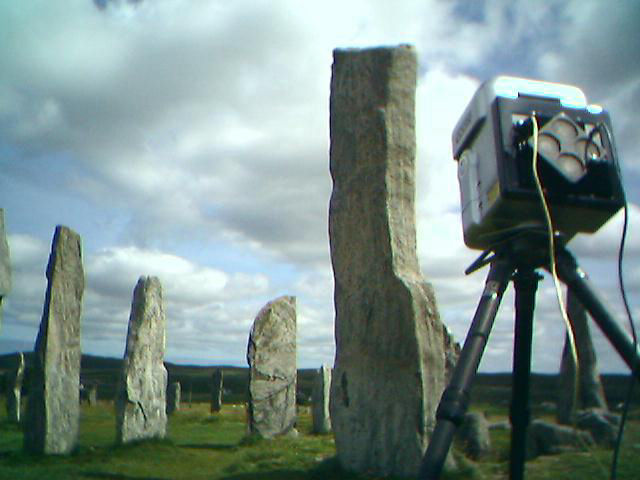
To achieve coverage of the entire megalithic setting, the scanner needs to be moved to different positions, or "stations". The scans are then "registered" together such that they are in the correct position with respect to each other then a final stage called "integration" generates a final 3D model.

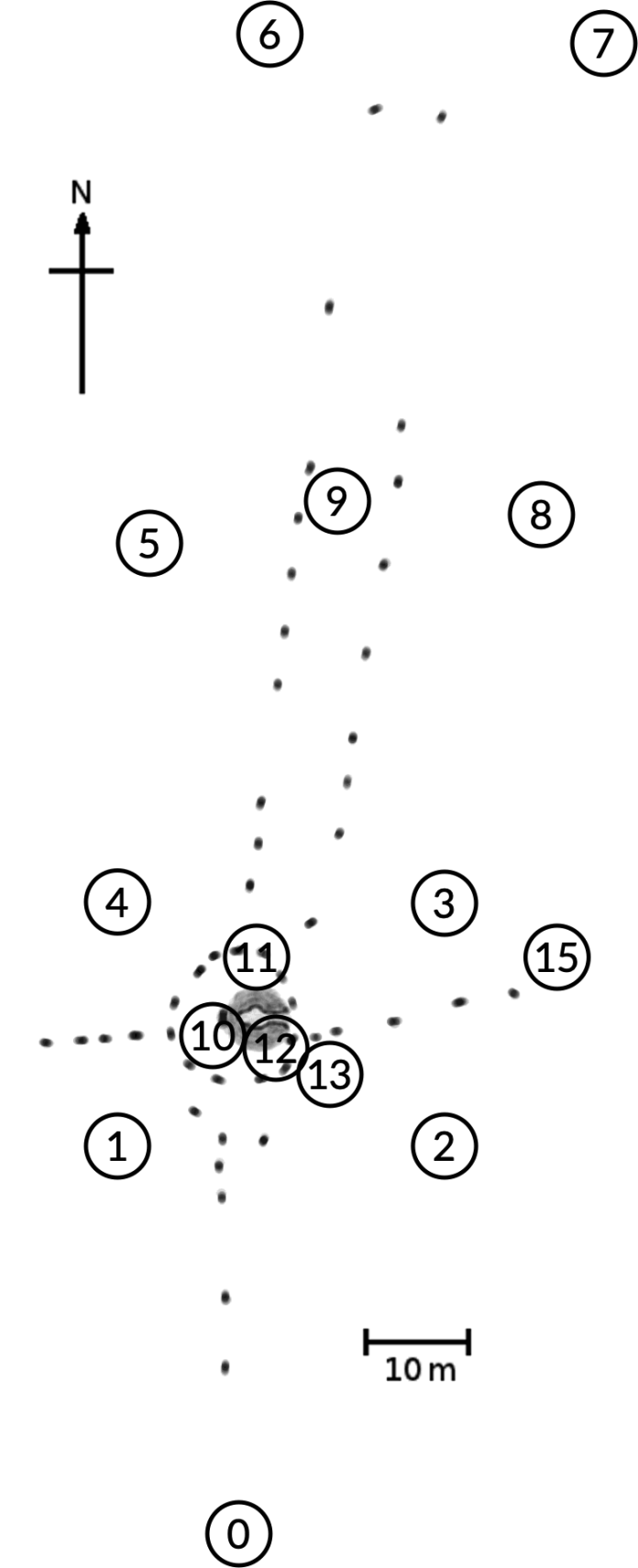
As the Callanish I monument is fairly spread out (approximately 150m north to south) and that we wanted dense scanning coverage of the megaliths, 14 stations were required to get coverage of all the stones from all angles.

The scanner typically would take a panoramic photograph which was then used for targetting of specific areas for high-resolution scanning. This enabled a two-pass approach of very high-resolution scanning of just the megaliths with a second pass of low-resolution scanning of the ground surface.

Scans were registered initially using three or four control spheres. These are white, ceramic spheres which are scanned at high-resolution from each station. The sphere centres are then calculated from the 3D data and the matching points are used to compute a transformation between the sphere centres at one station and the next station. A final registration pass of "mesh-to-mesh registration" was also done just to diffuse any sphere registration error.

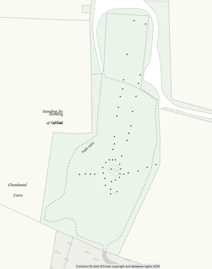
A handheld GPS was used to take control coordinates of each station which was adequate as a first pass for a georeferenced survey.

In total, over 50 million measurements were taken over three days.

Ordnance Survey Map of Callanish I

Ordnance Survey mapping of
Callanish I

Integration with Stellarium

The integration of the 3D model into Stellarium was a fairly straight-forward process albeit one with a few problems to solve.

The original dataset was not surveyed with high-accuracy ground coordinates. For archaeo-astronomical use, the alignment of the model with respect to the ground (and therefore sky) needed to be more accurate than the original survey data.

To resolve this issue, matching points were located on the 3D model and corresponding Ordnance Survey high-resolution mapping. In this case, the fence line surrounding the site was clearly visible on both datasets! We selected twelve key points and computed a transformation that georeferenced the 3D model to a few centimetres of accuracy.

The altitude of the model was calculated from a combination of GPS fixes taken on site at the twelve key points and from a topographical survey from the 1980s. This combination of datasets yielded a satisfactory levelling of the 3D model.

Horizon drawings from Ponting and Curtis

Horizon drawings from Ponting (1981) and Curtis (1994/2003)

Checking the Alignments

The final stage of the project was to check the alignments, skylines and simulations of major astronomical events within Stellarium.

Drawings from the primary archaeo-astronomical sources were also imported into Stellarium and minor adjustments were made based on inspection.

A number of interesting questions arose around exact locations the original drawings were taken from, for example, "in front of stone 8" and the height of the person/drawing table of the drawing!

© Copyright 2005- Archaeoptics/Callanish Blackhouse Tearoom - All Rights Reserved